Building a pedal from a DIY kit was my christmas project. After carefully wishing I got a BYOC Ping Pong Delay kit. Although the instructions were good (mostly really good, but a little obscure in two places) and the BYOC forum is amazing with really helpful people I figured out a few things on my own – so here they are, for your benefit.
Contents
This is a really long post, if you want just the fun stuff, just skip to Demo and Pictures.
Preparation
Soldering the PCB
Assembly
Troubleshooting
Paint
Demo and Pictures
Preparation
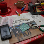 I haven’t really soldered in a long while, except to switch pickups in my guitars. I felt that didn’t go very well (I always got them working, but the solderings weren’t pretty and I struggled to get the lead where I wanted it). So I started, methodical man that I am, by reading a couple of guides on soldering on PCBs (printed circuit boards). That made a LOT of difference. This is the best of the ones I found: http://www.aaroncake.net/electronics/solder.htm
I also read the instructions for the pedal kit quite thoroughly (I had plenty of time before I could start the actual work). The sheer number of components was a bit intimidating, as was the sentence “This is our most difficult kit” in the preface of the instructions.
Soldering the PCB
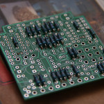 Since I’ve never actually soldered on PCBs I didn’t know which way was up – slightly embarrasing. I guessed correctly that the side with text on it (like “100K” for a 100 K ohm resistance) is the front side of the PCB, i.e. where the components go. The side without text is where the solderings go.
Once I established which way was up, soldering went really well. I did it in pretty poor lighting bent over a dinner table, but it was fine.
The instructions were good, but two things were rather annoying. The first was that when mounting the 0.1 uf capacitors, one is missing – the text says 14 and there are 14 slots on the PCB, but you only have 13. You have to go back to three pages to the resistor steps to find out one of them are supposed to be omitted. Surely this must be an editing error in the instructions, feels like someone pasted the line about omitting the capacitor in the wrong section. The second annoyance is that some of the capacitors are quite differently marked from what it says in the instructions, and to make things worse they are referred to as different colors from the ones shipped. Some of them are not polarized. An experienced builder would know that from the markings on the PCB, but it would be nice if it said so in the instructions.
Assembly
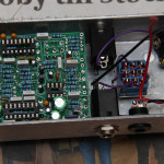 When the PCB was done, the next step was connecting the PCB to the rest of the components, like jacks, footswitch and the trim pots. This part was actually much less fun that soldering than the PCB. Wires don’t stay still like component pins. The pots and the led were mounted by adding them to the enclosure and then trying to make the pins match the holes in the PCB, lots of bending and adjusting and retrying.
Troubleshooting
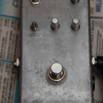 Once the assembly was done I put in a battery and pressed the footswitch and… nothing. I read up a bit in the instructions and found out you have to plug a cable into the input jack, it acts like a kind of activation switch. So I plugged in a cable and… nothing.
About half of the building instructions are made up out of troubleshooting. I got my DMM (Digital MultiMeter) and started checking connectivity and measuring voltage levels (I learned a lot from this stage – not least how to use a DMM). Everything checked out, but the pedal still wasn’t working.
So I turned to the BYOC forums. A bunch of extremely friendly and helpful people hang around there, and it doesn’t take many minutes to get great tips for solving your problem even when you’re a complete n00b with just 1 post. The general first reboot-your-computer-fixes-everything tip is to reflow all of the soldering points. Just warming up all of the joints, if needed add a little lead.
So that’s what I did – I removed the PCB from the enclosure, bent up the trim pots and reflowed all of the joints. Doing that I noticed I’d put the led in the wrong way – a real rookie mistake. I soldered it off the board and back on the right way – and started to get a little nervous I’d mixed up the orientation of other components.
I put everything back and pressed the footswitch, somewhere between hopeful that it would work and anxious that it wouldn’t and that I really had no idea what to do next to fix it. But as luck would have it – the LED lit up! I really had no proper equipment to test it right away – an acoustic with a really crappy pickup, and iPhone with AmpKit an Apogee Jam. Hooking it all up it just made strange noise, but strange noise with an echo! Problem is that with the signal chain being acoustic -> pedal -> jam -> iphone a really weak signal goes into the pedal and the preamping is done afterwards…
When I got home I plugged the pedal into the loop of my POD X3 Live and it just worked! (there’s a demo clip at the bottom of the post).
Paint
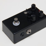 The final step was making it pretty. I realized right away I had done things in the right order. The components were mounted in the enclosure and I couldn’t disassemble it without soldering off a few wires. I chose to just lift out the PCB so the pots didn’t stick out of the enclosure and taped the bottom shut with masking tape. I sanded the enclosure to get it smooth and wiped it down with chemical gasoline and sprayed away – about five layers.
The paint job turned out pretty good – with one exception. The masking tape got stuck in the paint so when I removed it chips of the paint came off. Knowing what I know now I would have done the enclosure first or taken the time to completely remove the components. Now I think I will just sand the chipped egdes and try to put a couple of extra layers just around that area.
Demo and Pictures
Here’s a demo of what the pedal sounds like in different settings:
[soundcloud id=’32688014′]
Pictures of how I got from a set of components to a working pedal:
[slickr-flickr search=”sets” set=”72157628735983515″ items=”50″ use_key=”y” sort=”date” order=”ascending”]

